

Strona zostanie usunięta „Introduction”. Bądź ostrożny.
Introduction
edgard.palza edytuje tę stronę 8 lat temu
The application "Cyber Physical Systems Model" is a software, developed by students of the TU Darmstadt in affiliation with the Telecooperation Group (TK).
This software is designed with the goals of facilitating the modeling and improving the visualization and scalability of SmartGrids, as well as to make the most complete, intuitive and user-friendly tools available for the user. Moreover, provide the user the possibility of using different perspectives of visualization of the system and different tracking layers for a more precise analysis.
The software offers a variety of features, such as the creation of new components, as well as its manipulation through graphs for a more personalized use, various modeling layers and analysis of personalized components through graphs and statistics.
At first instance, the software supports only electrical connections and components, such as home appliances and energy generators. For future extensions, it could be considered the implementation of internet connections, water flows, and gas usage.
I. Smart Grid
Smart Grid is an electricity network based on digital technology, which contains numerous components, such as smart appliances, renewable energy resources, and energy efficient resources [1]. It has the capability of monitor, analyze, control and communicate the production and distribution of energy. throughout the network.
Today, a modern Smart Grid has the capabilities of repairing itself, ensure consistency and resist power leakages, as well as respond to energy demand and Load Handling, in a not stable network [2]. Another key feature of Smart Grids is the decentralization of energy production, where the energy production comes from various power plants, solar parks, and private energy sources.
II. Distribution of the Documentation:
The documentation is distributed into 3 main parts:
- The User Manual, a quick guide for anyone, who wants to get involved with the modeling of SmartGrids. Therefore, this section describes the functionalities, such as the creation of the network and modification of internal elements as well as shortcuts for a better and faster user’s experience. The distribution of the program is also detailed through pictures and examples.
- Code documentation describes the main parts of the program code, such as the MVC pattern, architecture and the different classes and categories. This documentation is intended to explain the code to future developers, who want to get involved with the implementation of the software, as well as for the community.
- Algorithms: (…)
III. Description of Terms:
At this point, it is indispensable to explain some important terms, which will be frequently used on future sections:
Holon World:
A Holon can be an entity environment as well as a part of it at the same time. Each Holon is an autonomous, cooperative and recursive entity, that communicates with its environment, better known as Holon World [3]. The Holon World has of the following components:
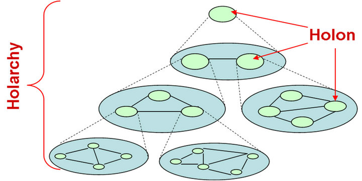
Image Credit: [3]- A Holon Object is a component that can be directly connected to the network through Holon Edges. It can modify the network by consuming or producing energy. Each Holon Object contains a finite amount of Holon Elements, which determine if the Holon Object is a consumer or a producer. For instance, a Holon can be represented by a house, as a pure energy consumer, or a power plant, as a pure energy producer, or an hospital, which consumes and produces energy at the same time. In the software, each Holon Object contains the following properties: a unique ID, an editable name, a list of Holon Elements and a list with connections.
- Holon Element refers to components, integrated to Holon Objects. Each Holon Element either produces or consumes energy, but not both at the same time. Some typical examples for consumption of energy are TVs or radios and for production of energy are solar panels or energy generators.
- A Holon Switch allows the manipulation of the energy flow throughout the entire network. It is typically used to determine the energy flow direction on the network. Each Holon Switch has a unique ID, an editable name and a list of connections.
- A Holon Edge is a connection between two components (component 1 and component 2) on the network. Each Holon Edge has a source (component 1) and a destination (component 2) of energy, as well as a maximum capacity and current energy flow.
- Holon Node represents an empty Holon, which neither produces nor consumes energy.
An Object is used in this context as a generalization for Holon Object, Holon Switch, Holon Node and/or Holon Edge.
A Subnet is a subdivision of the network. Subnets are ruled by Holon Switches and Holon Edges. For example, two houses belong to the same Subnet, if both are connected through a Holon Edge or through a Holon Edge-Holon Switch-Holon Edge and the Holon Switch is closed, else they belong to two different Subnets.
An UpperNode is a group of Objects. UpperNode has no modeling restriction, such as the amount of Objects or type of Objects. The UpperNode can be defined and constructed by the user through the option “Group” (refer to User Guide, section II.1 for more information). Please consider the difference between UpperNode and Subnet. A great example could be the split of a country into counties and these into cities.
Flexibility is a variable possessed by every Holon Element of every Holon Object on the network, which can be either positive, negative or neutral. It is typically used in emergency scenarios, such as lack or overproduction of energy from the grid. Holon Elements with high Flexibility are Batteries and Power Regulators.
Time Step is an instance of the network. Time Steps are be found at the bottom of the screen (refer to User Guide, section III for more information).
Simulation is a state of the program that can be accessed by clicking the play button at the bottom of the screen (refer to User Guide, section III for more information). The state of Simulation differs mainly from the Modeling state, by taking the previous status of the network into account. For example, if a Holon Edge breaks in one Time Step at the next one, it will remain broken.
[1] https://en.wikipedia.org/wiki/Smart_grid
[2] https://www.techopedia.com/definition/692/smart-grid
[3] Ebisa Negeri, Nico Baken and Marjan Popov, “Holonic Architecture of the Smart Grid”, 2013, http://file.scirp.org/pdf/SGRE_2013052913482779.pdf
Usuń stronę